Fine Beautiful Agility Brake Controller Wiring Diagram Examples
Electric Trailer Brakes General Installation R And P Carriages Cargo Utility Dump Equipment Car Haulers And Enclosed Trailers In Chicago Ottawa Dekalb And Joliet Il
Be sure to wire by function only. Connect black wire through an automatic reset circuit breaker 20 amp for 1 2 axles 30 amp for 3 4 axles to the positive terminal of the battery. If your vehicle is not equipped with a plug and play harness you can also splice in wiring for connecting a brake controller. This diagram shows the stock tcc torque converter clutch and brake light switch with the yellow wire feeding through the switch and con tinuing down to the a terminal on the connector going into the transmission. Redline brake controller wiring diagram source. The black wire will be connected to the positive battery terminal via 20 or 30 amp circuit breaker as specified in the brake controller instructions. To the function wires under the dash. Find your agility trailer brake controller wiring diagram here for agility trailer brake controller wiring diagram and you can print out. You will need to use a circuit. Installing a brake controller involves disconnecting the vehicle battery mounting the brake controller onto dash and plugging the unit in with a vehicle specific wiring harness.
The white wire on the brake controller will be connected to the negative battery terminal.
The white wire on the brake controller will be connected to the negative battery terminal. To install the hopkins agility brake controller hm47294 on your vehicle you will need to install a 4 pole trailer connector at the rear of your vehicle and then hardwire the remaining wires to the vehicle. This diagram shows the stock tcc torque converter clutch and brake light switch with the yellow wire feeding through the switch and con tinuing down to the a terminal on the connector going into the transmission. The blue wire will connect to the white wire in the duplex cable that you ran up earlier. There is no wiring adapter available for your 1995 chevy 1500 silverado. Redline brake controller wiring diagram source.
The wiring adapter that comes with the hopkins agility brake controller proportional w gm adapter hm47294. Find your agility trailer brake controller wiring diagram page 4 here for agility trailer brake controller wiring diagram page 4 and you can print out. The red stoplight wire must be connected to the cold side of the brake pedal stoplight switch. In this guide we cover step by step how to install a brake controller. Search for agility trailer brake controller wiring diagram page 4 here and subscribe to this site agility trailer brake controller wiring diagram page 4 read more. Search for agility trailer brake controller wiring diagram here and subscribe to this site agility trailer brake controller wiring diagram read more. The blue wire will connect to the white wire in the duplex cable that you ran up earlier. You will need to use a circuit. White wire ground negative terminal on battery blue wire trailer electric brakes black wire positive terminal on battery red wire cold side of stop lamp switch or brake light. Redline brake controller wiring diagram source.
If your vehicle is not equipped with a plug and play harness you can also splice in wiring for connecting a brake controller. Be sure to wire by function only. The red wire will be connected to the stoplight switch near the brake pedal which only has signal when the brakes are applied. Search for agility trailer brake controller wiring diagram here and subscribe to this site agility trailer brake controller wiring diagram read more. Redline brake controller wiring diagram source. The blue wire will connect to the white wire in the duplex cable that you ran up earlier. In this guide we cover step by step how to install a brake controller. White wire ground negative terminal on battery blue wire trailer electric brakes black wire positive terminal on battery red wire cold side of stop lamp switch or brake light. This diagram shows the stock tcc torque converter clutch and brake light switch with the yellow wire feeding through the switch and con tinuing down to the a terminal on the connector going into the transmission. Find your agility trailer brake controller wiring diagram page 4 here for agility trailer brake controller wiring diagram page 4 and you can print out.
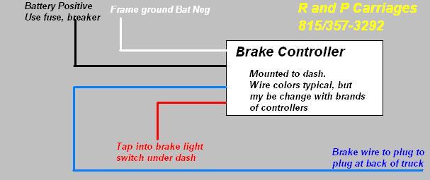
The red wire will be connected to the stoplight switch near the brake pedal which only has signal when the brakes are applied. This diagram shows the stock tcc torque converter clutch and brake light switch with the yellow wire feeding through the switch and con tinuing down to the a terminal on the connector going into the transmission. The wiring adapter that comes with the hopkins agility brake controller proportional w gm adapter hm47294. The black wire will be connected to the positive battery terminal via 20 or 30 amp circuit breaker as specified in the brake controller instructions. The white wire on the brake controller will be connected to the negative battery terminal. Be sure to wire by function only. Connect black wire through an automatic reset circuit breaker 20 amp for 1 2 axles 30 amp for 3 4 axles to the positive terminal of the battery. You will need to use a circuit. Installing a brake controller involves disconnecting the vehicle battery mounting the brake controller onto dash and plugging the unit in with a vehicle specific wiring harness. When you employ your finger or even the actual circuit together with your eyes it is easy to mistrace the circuit.
For ease of convenience the kit is supplied with the yellow wire and a black grounding wire attached to a connector that will plug directly into the transmission. Installing a brake controller involves disconnecting the vehicle battery mounting the brake controller onto dash and plugging the unit in with a vehicle specific wiring harness. To the function wires under the dash. To install the hopkins agility brake controller hm47294 on your vehicle you will need to install a 4 pole trailer connector at the rear of your vehicle and then hardwire the remaining wires to the vehicle. Find your agility trailer brake controller wiring diagram page 4 here for agility trailer brake controller wiring diagram page 4 and you can print out. When you employ your finger or even the actual circuit together with your eyes it is easy to mistrace the circuit. White wire ground negative terminal on battery blue wire trailer electric brakes black wire positive terminal on battery red wire cold side of stop lamp switch or brake light. You will need to use a circuit. Search for agility trailer brake controller wiring diagram page 4 here and subscribe to this site agility trailer brake controller wiring diagram page 4 read more. The blue wire will connect to the white wire in the duplex cable that you ran up earlier.
Find your agility trailer brake controller wiring diagram here for agility trailer brake controller wiring diagram and you can print out. The black wire will be connected to the positive battery terminal via 20 or 30 amp circuit breaker as specified in the brake controller instructions. Redline brake controller wiring diagram source. If your vehicle is not equipped with a plug and play harness you can also splice in wiring for connecting a brake controller. For ease of convenience the kit is supplied with the yellow wire and a black grounding wire attached to a connector that will plug directly into the transmission. Find your agility trailer brake controller wiring diagram page 4 here for agility trailer brake controller wiring diagram page 4 and you can print out. The blue wire will connect to the white wire in the duplex cable that you ran up earlier. The white wire on the brake controller will be connected to the negative battery terminal. Search for agility trailer brake controller wiring diagram here and subscribe to this site agility trailer brake controller wiring diagram read more. The red wire will be connected to the stoplight switch near the brake pedal which only has signal when the brakes are applied.